| Back to the Plastic Scale Modeling page |

|
|
Whittle W.1 Jet Engine 1/72 scale scratchbuilt by Michael Morrow 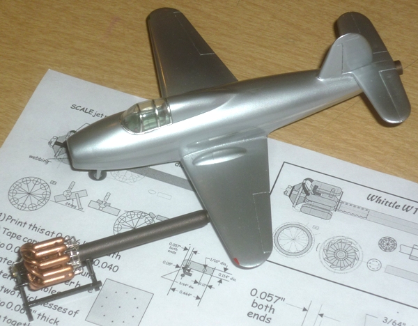
|
I built this 1/72 scale model of the Whittle W.1 jet engine, the first British production jet engine, to accompany my Gloster Whittle prototype model (build posted
here). The two models are shown together above, just before installation in the NWSM 'X-Planes' display at the Museum of Flight, which will run from December 2015 to the beginning of March 2016.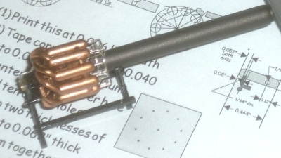 The model is scratchbuilt, mostly from brass tubing, rod, and sheet, along with some aluminum block, copper wire, silver wire, and plastic sheet.
 |
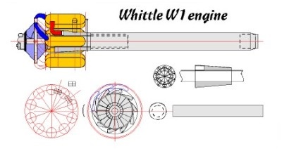 A working drawing was cobbled together from several sources and scaled to 1/72, and then the difficult task of sourcing appropriately-sized materials began, along with the acquisition of the needed drill bit sizes, none of which turned out to be standard. GRAINGER was invaluable as a source for the odd drill bit sizes. The drawing shown here is fit-to-page scale, not 1/72!
 |
|
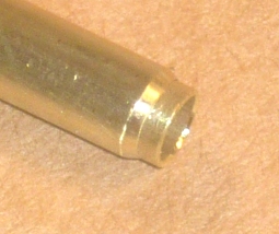
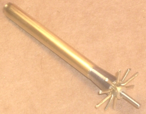
The Build I started with the jet pipe, as it was the easiest. A simple brass tube cut to the correct length and tapered on the end, with a small telescoping section thinned on the inside to look scale thickness, a couple of drops of C/A, and it was done. 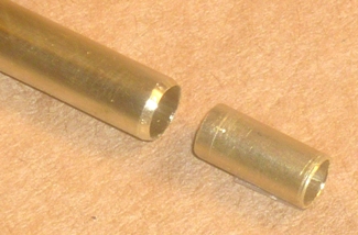
 |
|
Next up was the exhaust collector chamber. This I turned from aluminum on a poor man's lathe, my old Moto-Tool. The first step was to lay out the holes in the part. A center hole was needed for the mandrel, and ten equally-radially-spaced holes for the combustion chamber exhaust pipes to exhaust in to. Here I've taped a 1/72 scale drawing of the collector to a piece of 0.5" thick aluminum barstock so the holes can be center-punched. 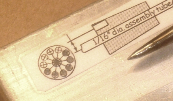 |
A magnifying glass helped to get the holes center-punched as reasonably as my Mark I eyeballs could expect . . .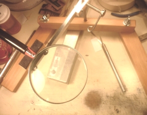
|
. . . and here's the result - a bunch of center-punched holes ready to be drilled . . .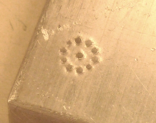 |
The holes all drilled, the outer diameter scribed, ready to cut out and turn down . . .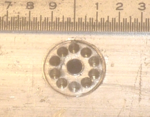
|
. . . and the final part turned down to size, tapered, and cut to length . . .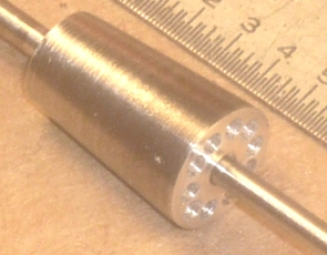
|
The holes the exhaust pipes will fit in to. . .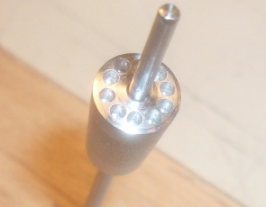
|
. . . ten exhaust pipes fitted - outer ends to be trimmed later.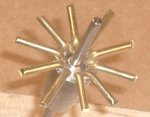
|
 Here're the major components fitted together so far - from left to right, the jet tube, the exhaust chamber with exhausts fitted, and some small sections of brass tubing representing the back of the impeller section.
Inside the front of the jet pipe I C/A'd concentric rings of telescoping tubing, the innermost being 1/16" I.D. This allows the jet pipe to slide right onto the 1/16" piano wire assembly mandrel, making assembly of the major components very simple. |
The engine assembly mounted on a temporary stand. So far, so good.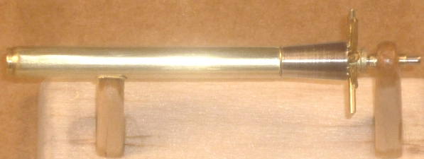
|
Next up, the ten identical combustion chambers. I'm using brass rod for the combustion chambers. The first step is to cut ten combustion chamber blanks of identical length, accomplished using the poor-man's cut-off saw, a trusty 'ol Moto-Tool, in a suitable, if somewhat crude fixture.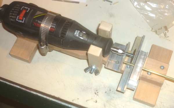
Speaking of high-revving Moto-Tools fitted with easily-exploded cutting disks, now seems like a good time to mention safety. Safety glasses. Harbor Freight. 99 cents on sale. A whopping $1.50 not on sale. Buy multiple pair so there's one near each tool and always available. 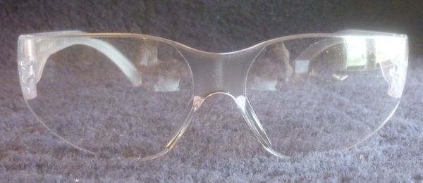
|
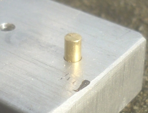 I've cut ten identical-length combustion chamber blanks (plus a few spares). There needs to be a centered hole in the aft end for the tiny (fuel/ignition lines?) to fit into, and it needs to be done before the ends are rounded. A simple fixture for that purpose was made by drilling a hole in a piece of aluminum block just a couple thousandths bigger than the blank. Slip the brass blank into the hole, center-punch the end to make drilling easier, and drill the itty-bitty hole using a drill press. Here's the blank in the hole, ready to be end-drilled . . .
So how do you drill a 0.024" hole in the end of a 0.114" diameter rod? Weeeelllll . . . I clamped the tiny little drill into a pin-vise, and then chucked the pin-vise into the drill press. Getting the headstock wobble to be less than the drill size was entertaining, to say the least. To make the fore/aft alignment of the combustion chambers as near identical as possible, the exhaust pipe mounting hole was drilled next. I had to make a fixture for this. |
Two pieces of aluminum block were clamped together and a hole drilled down the center . . .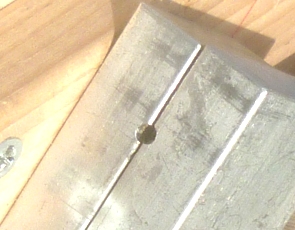
|
. . . resulting in two pieces of block with half-round slots for the blanks to rest in . . .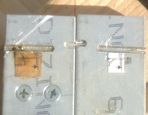
|
|
A hole was drilled for a stop pin in one of the slots, and a stop pin fitted (left side of right picture). Each blank was fitted against the stop pin, center-punched the correct distance from the end, and drilled for the exhaust pipe. I had originally drilled matching angled holes in the opposite end of the blanks for the balance pipes to fit into, but I ended up not using them due to alignment difficulties. |
|
Next, the ends are turned round. The Moto-Tool had an accessory collet that was nearly the perfect size to accept the little combustion chamber blanks. |
|
Each blank was chucked up, and the ends turned round . . . 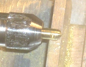
|
. . . resulting in 10 tiny little as near-identical combustion chambers as I could manage . . .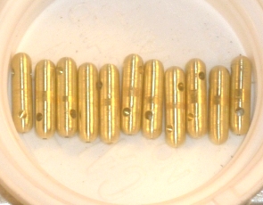
|
|
An impeller assembly was built up of brass tubing, brass sheet, and plastic sheet around a core made from 1/16" I.D. brass tubing. 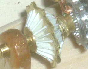
|
The 1/16" I.D. tubing core allowed the finished assembly to slide right onto the 1/16" dia. mandrel wire. 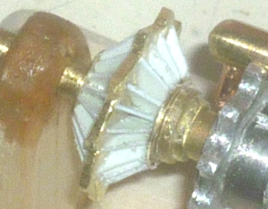
|
|
Fore and aft combustion chamber mounting cradles (not scale, but they can't really be seen on the finished model) were made from aluminum sheet . . . 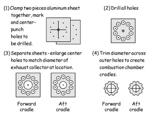
|
. . . carefully aligned, and glued in place on the exhaust chamber as attach points for the combustion chambers, and to keep the combustion chambers in proper alignment. 
|
. . . the whole assembly up to this point . . .
|
|
Ten intake pipes radiate from the impeller assembly to the ten combustion chambers. The intake pipe enters the combustion chamber on the front end at a 45 degree angle from both the vertical plane (looking down from above), and from the horizontal plane (looking from the front). A fixture was needed to make a hole in each combustion chamber where the intake pipe would be attached. |
 The fixture previously used to drill the exhaust pipe exit attach hole in each combustion chamber was modified to present a combustion chamber in the proper orientation to drill the intake pipe hole. Here's the modified fixture - note the aluminum carrier block at 45 degrees to the first wood base, which is itself mounted at 45 degrees to the bottom wood base. Here you can see a combustion chamber fitted into the fixture.
 |
The fixture holds a combustion chamber in the proper position so a small jewel's file, held horizontally, can be used to file a flat spot exactly where the hole needs to be drilled. Because the end of the combustion chamber is hemisphical, the flat spot filed is circular. 
|
. . . the circular spot that's been filed . . .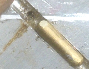
|
. . . and the circular spot center-punched.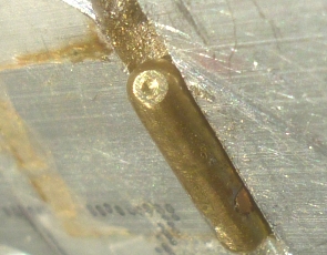
|
|
The intake hole ready to be drilled . . . 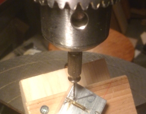
|
. . . the intake hole drilled for the intake pipe. 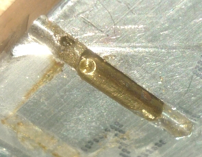
|
|
The previously fitted combustion chamber exhausts . . .
|
. . . need to be trimmed fairly short for the combustion chambers to be mounted on . . . 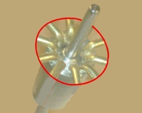
|
Most of the major parts are now done, so it's time to start assembly. The graphic below shows how the pieces go together. The main components are slipped onto the 1/16" diameter assembly rod (1/16" dia. music wire) - the brass spacers on the left of the exhaust collection chamber (with its combustion chamber mounts), and the jet pipe on the right, but I left the impeller assembly off until the combustion chambers were all installed so that it could be properly aligned with the combustion chambers. A couple of drops of C/A sufficed to hold it all together.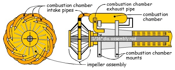
|
|
How it looks in metal and plastic with the impeller assembly provisionally slipped on. One combustion chamber and its exhaust pipe has been installed - you can just barely see the copper-colored exhaust pipe leading from the front of the combustion chamber to the aluminum center chamber . . . 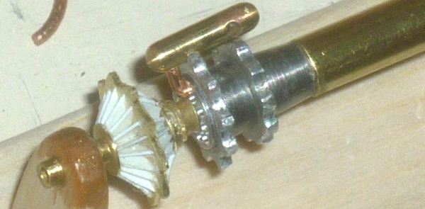
|
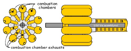 This shows the front and side views with all the combustion chambers installed, including their exhaust pipes which feed into the aluminum center chamber . . .
|
 The impeller assembly added - the impeller assembly needs to be properly aligned with the combustion chambers in the front view, so that the combustion chamber intake pipes are properly located. I've shown one of the intake pipes in the front view to show how it leaves an impeller exit, skips past one combustion chamber, and enters the next chamber in line.
|
|
Time to add the combustion chamber intake pipes. I used 0.050 soft copper wire, wrapped around a cylindrical rod to get the correct curvature. Here I've clipped a piece off to begin fitting it between the impeller exit and the combustion chamber intake hole. 
|
Fit a curved pipe into a hole in a combustion chamber, trim to length at the impeller exit, file flat to match the rectangular impeller exit, and glue in place with C/A. The impeller assembly is painted gloss black, and here's how the pipes will fit when they've been added . . . 
|
|
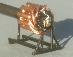
Here's the completed engine sitting in the evening sun. I've also added the balance tubes between the combustion chambers at the rear of the combustion chambers. If you're a STAR WARS fan, one of the components of the balance tubes used on a later version of this engine in the Gloster Meteor jet fighter, was used as the emitter of Obi-Wan Kenobi's lightsaber. All the model needs now is painting, the addition of some small details on the front, and a proper engine stand. 
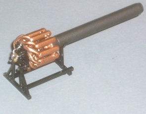
Here I've added some small details to the front of the engine, painted the combustion chambers copper, painted the jet pipe Burnt Iron, and made a proper engine stand for the W1. |
|
|
|
Putting it all into perspective - the almost completed engine alongside a ruler. The engine itself is about 0.61" in diameter (just under 5/8"), and about 0.77" long (just over 3/4"). Add the jet pipe, and the total length is just 2.69" long. 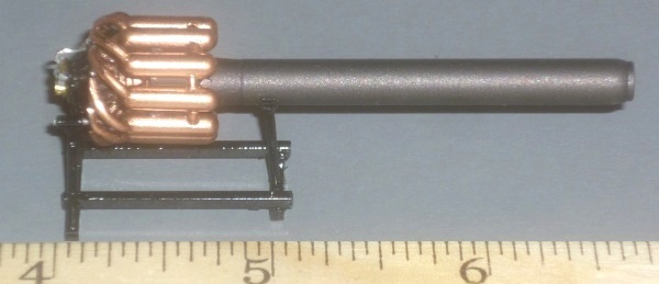
|
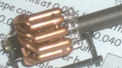 The final details added:
- the set of fine piping that exits from the aft end of each combustion chamber and feeds into two small rings around the aft end of the jet engine . . . . . . and it's done! Just in time to go into the display case.  |
The display cases at the MoF . . .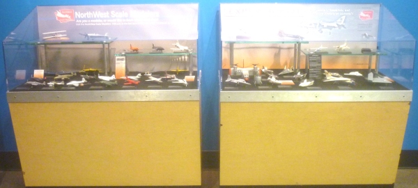 The Whittle is in the left case . . . 
. . . . right . . . . about . . . here ------^ My contributions to the display - The He-178, Gloster E.28/39 Pioneer (Whittle) aircraft, and Whittle W1 turbojet engine. The Ohain turbojet engine in front of the He-178 is the work of NWSM member Steve Galacci. 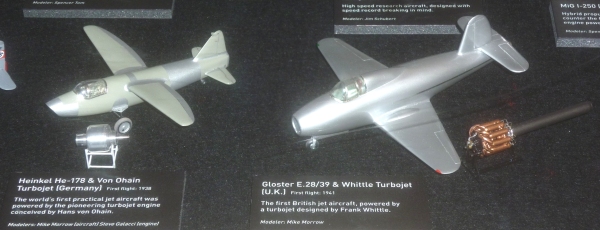 The Gloster and the Whittle W1 - taking pictures through plexiglass in a dark room of a subject on a black surface? Not easy. 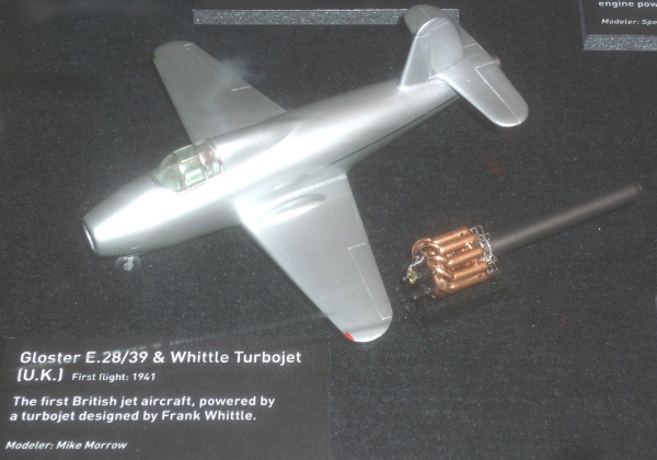 The Whittle W1. On a black felt surface. Should have made a piece of plastic faux concrete tarmac for it to sit on so it would show up better. 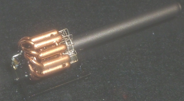 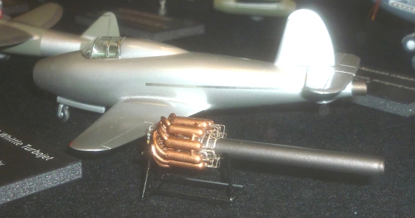 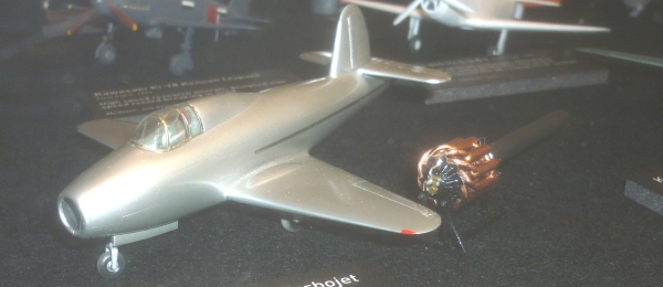
|
| Back to the Plastic Scale Modeling page |
|